
293-HL-CP
BERG Manual Hydro-mechanical Self-locking C-clamping Systems
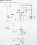
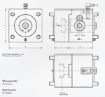
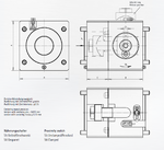
Manually movable quick die changing system with hydrolock C-clamping
")
")
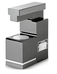
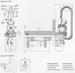
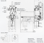
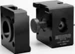
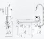
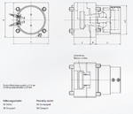
The hydromechanical self-locking (hydrolock) C-clamping die clamping system is designed for clamping dies of various widths on press slides. The clamping actuator can be moved manually in the T-slot of the press slide between the parking position and the respective die. Hydraulic pressure is at a maximum 90 bar.
![]() PDF Data Sheet: BERG Manual Hydro-mechanical Self-locking C-clamping Systems (293-HL-CP)
PDF Data Sheet: BERG Manual Hydro-mechanical Self-locking C-clamping Systems (293-HL-CP)
For more information regarding this item (BERG Manual Hydro-mechanical Self-locking C-clamping Systems) or other items, fill out the form below
or contact our office directly:
Telephone: 815-962-5600
Fax: 815-962-4600
Location: 304 North Main St, Suite 104, Rockford, IL 61101-1101 USA
Email: infο@ΤΑCRοckfοrd.cοm
Related
Manual Hydro-mechanical Self-locking Drawbar Style Clamping Systems
The hydromechanical self-locking (hydrolock) drawbar style die clamping system is designed for clamping dies of various widths on press slides. The clamping actuator can be moved manually in the T-slot of the press slide between the parking position and the respective die. Hydraulic pressure is at a maximum 90 bar.
Automatic Hydro-mechanical Self-locking C-clamping Systems
The C-clamping hydromechanical self-locking (hydrolock) die clamping system is designed for clamping dies of various widths on press slides. The clamping actuator moves automatically in the T-slot of the press slide between the parking position and the respective die. Clamping and unclamping are performed by a hydromechanical self-locking clamping gear. Hydraulic pressure is at a maximum of 90 bar.
Automatic Hydro-mechanical Self-locking Drawbar Style Clamping Systems
The drawbar style hydromechanical (hydrolock) self-locking die clamping system is designed for clamping dies of various widths on press slides. The clamping actuator moves automatically in the T-slot of the press slide between the parking position and the respective die. Clamping and unclamping are performed by a hydromechanical self-locking clamping gear. Hydraulic pressure is at a maximum 90 bar.
Transfer Rail Couplings
The mechanical self-locking Berg gripper rail coupling GSM is designed for manual coupling of gripper rails on transfer presses. A vertical lift-out stroke is required for changing the tool.

Manual Mechanical Self-locking Drawbar Style Clamping Systems
The manually actuated drawbar style die clamping system is designed for clamping dies of various widths on press slides and tables. The self-locking eccentric cam gear guarantees a simple handling with a maximum of safety.
Automatic Electromechanical Drawbar Style Clamping Systems
The electro-mechanical self-locking drawbar style clamping system is designed for quick clamping dies of different widths with clamping slot on press slides.
The clamping systems are controlled de-centrally and individually in each clamping system. Each local clamp control system communicates with the pressing machine control system. The clamping actuator automatically moves into the T-slot of the press slide between the parking position and the respective die. The electro-mechanical clamping system clamps the die and switches off automatically on reaching the clamping force.
Hydro-mechanical Self-locking Transfer Rail Couplings
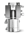
The hydromechanical self-locking gripper rail coupling is designed for automatic coupling of gripper rails on transfer presses. A vertical lift-out stroke is required for changing the tool. The coupling consists of a hard anodized aluminum housing, an axially movable tensioning rod and a hydromechanical self-locking clamping gearing. This configuration allows for high clamping forces and features a very high dynamic rigidity with minimum mass.
Manually Operated Eccentric Cam Style Transfer Rail Couplings
The mechanical self-locking gripper rail coupling is designed for manual coupling of gripper rails on transfer presses. A vertical life-out stroke is required for changing the tool. The coupling consists of a hard anodized aluminum housing, an axially movable tensioning rod and a self-locking eccentric cam gearing. This configuration allows high clamping forces and features a high dynamic rigidity with minimum mass.
Manually Operated Swing-out Style Transfer Rail Couplings
The mechanical self-locking swing-out style gripper rail coupling is designed for manual coupling of gripper rails on transfer presses. A short lift-out stroke is required for changing the tool. An axial stroke is required in the event of additional centering with pins. The coupling consists of a hard anodized aluminum housing, a swiveling tensioning rod and a self-locking eccentric cam gearing. This configuration allows high clamping forces and features a high dynamic rigidity with minimum mass.