
470.110.850.000
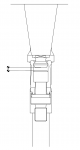
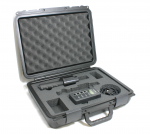
50 Drawbar Stroke Verification Gauges
")
")

For more information regarding this item (50 Drawbar Stroke Verification Gauges) or other items, fill out the form below
or contact our office directly:
Telephone: 815-962-5600
Fax: 815-962-4600
Location: 304 North Main St, Suite 104, Rockford, IL 61101-1101 USA
Email: infο@ΤΑCRοckfοrd.cοm
Related
Drawbar Stroke Verification Gauges
Prevents gripper failures, spindle and tool holder taper damage, and "stuck" tool holders.
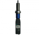
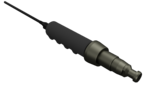
HSK Drawbar Sensor Position Gauges
Drawbar position gauges are used to adjust and set drawbar stroke position on HSK machine tool spindles. The gauges allow the clamping angle to be adjusted to the high and low limits, allowing the stroke position to be set.
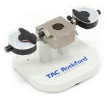
Series 968 HSK Tool Holder Taper Gauges
Series 968 gauges offer comprehensive dimensional verification of HSK tool holders.
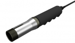
Drawbar Clamping Measuring Bars
This critical performance -- the tool clamping force -- is often never measured after a machine is put into service. Regular verification allows problems to be detected early so maintenance and repairs can be scheduled. As a result, emergencies and unexpected downtime can be avoided. When troubleshooting, drawbar performance can quickly be verified.

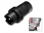
Drawbar Clamping Force Gauges, Wired
Tool clamping force is often never measured after a machine is put into service. Regular verification allows problems to be detected early so maintenance and repairs can be scheduled. As a result, emergencies and unexpected downtime can be avoided. When troubleshooting, drawbar performance can quickly be verified.
Machine-Integrated Drawbar Force Gauges
The machine-integrated drawbar force gauge automates drawbar force measurement. With a wireless force sensor stored in the tool changer, a machine can periodically automatically check the drawbar without stopping production. Drawbar force is returned to the machine control via a wireless receiver, automatically alerting the operator if insufficient force is detected.
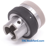
Workholding Collet Drawbar Force Gauge
ForceCheck collet force gauges measure the drawbar pullback force of a 5C, 16C, or 20C collet workholding system. Measurement of collet drawbar force provides an easy way to ensure correct force from machine to machine, or between setups for different parts.
Kennametal (KM Taper) Drawbar Force Gauges
Measuring bars, complete sets, and base units for measuring drawbar force on a Kennametal KM spindle.
Steep Taper (ISO) Drawbar Force Gauges
Measuring bars, complete sets, and base units for measuring drawbar force on a Steep Taper (SK) ISO standard spindle.
Automatic Hydraulic Drawbar Style Clamping Systems
The hydraulic die clamping system with drawbar style clamping is designed for clamping dies of different widths on press slides. The clamping actuator moves automatically into the T-slot of the press slide between the parking position and the respective die. The clamping element can clamp different clamping rim heights due to the long clamping stroke of the double acting cylinder. Hydraulic pressure is at a maximum 400 bar.