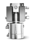
293-GSH
BERG Hydro-mechanical Self-locking Transfer Rail Couplings
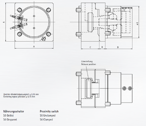
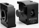
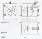
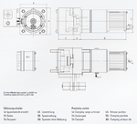
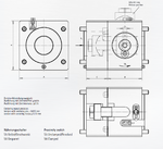
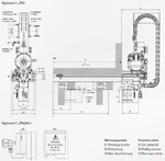
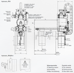
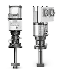
The hydromechanical self-locking gripper rail coupling is designed for automatic coupling of gripper rails on transfer presses. A vertical lift-out stroke is required for changing the tool. The coupling consists of a hard anodized aluminum housing, an axially movable tensioning rod and a hydromechanical self-locking clamping gearing. This configuration allows for high clamping forces and features a very high dynamic rigidity with minimum mass.
![]() PDF Data Sheet: BERG Hydro-mechanical Self-locking Transfer Rail Couplings (293-GSH)
PDF Data Sheet: BERG Hydro-mechanical Self-locking Transfer Rail Couplings (293-GSH)
For more information regarding this item (BERG Hydro-mechanical Self-locking Transfer Rail Couplings) or other items, fill out the form below
or contact our office directly:
Telephone: 815-962-5600
Fax: 815-962-4600
Location: 304 North Main St, Suite 104, Rockford, IL 61101-1101 USA
Email: infο@ΤΑCRοckfοrd.cοm
Related
Transfer Rail Couplings
The mechanical self-locking Berg gripper rail coupling GSM is designed for manual coupling of gripper rails on transfer presses. A vertical lift-out stroke is required for changing the tool.
Manually Operated Eccentric Cam Style Transfer Rail Couplings
The mechanical self-locking gripper rail coupling is designed for manual coupling of gripper rails on transfer presses. A vertical life-out stroke is required for changing the tool. The coupling consists of a hard anodized aluminum housing, an axially movable tensioning rod and a self-locking eccentric cam gearing. This configuration allows high clamping forces and features a high dynamic rigidity with minimum mass.
Electromechanical Transfer Rail Couplings
The electro-mechanical gripper rail coupling is designed for automatic coupling of gripper rails on transfer presses. A vertical lift-out stroke is required for changing the tool. The coupling consists of a hard anodized aluminum housing, an axially movable tensioning rod and an electromechanical self-locking helical gearing. This configuration achieves a very high repeat precision, high clamping forces, and features dynamic rigidity with low mass.
Manually Operated Swing-out Style Transfer Rail Couplings
The mechanical self-locking swing-out style gripper rail coupling is designed for manual coupling of gripper rails on transfer presses. A short lift-out stroke is required for changing the tool. An axial stroke is required in the event of additional centering with pins. The coupling consists of a hard anodized aluminum housing, a swiveling tensioning rod and a self-locking eccentric cam gearing. This configuration allows high clamping forces and features a high dynamic rigidity with minimum mass.
Automatic Hydro-mechanical Self-locking C-clamping Systems
The C-clamping hydromechanical self-locking (hydrolock) die clamping system is designed for clamping dies of various widths on press slides. The clamping actuator moves automatically in the T-slot of the press slide between the parking position and the respective die. Clamping and unclamping are performed by a hydromechanical self-locking clamping gear. Hydraulic pressure is at a maximum of 90 bar.
Automatic Hydro-mechanical Self-locking Drawbar Style Clamping Systems
The drawbar style hydromechanical (hydrolock) self-locking die clamping system is designed for clamping dies of various widths on press slides. The clamping actuator moves automatically in the T-slot of the press slide between the parking position and the respective die. Clamping and unclamping are performed by a hydromechanical self-locking clamping gear. Hydraulic pressure is at a maximum 90 bar.
Overview: Clamping Systems with AS-Interface
The BERG AS-Interface clamping and chucking systems are intended for clamping various tools/dies on press slides and black holders, and for sliding table clamping and gripper rail couplings on multiple die presses. They are used on new machines and for retrofitting automatic clamping systems in existing press lines.
Manual Hydro-mechanical Self-locking C-clamping Systems
The hydromechanical self-locking (hydrolock) C-clamping die clamping system is designed for clamping dies of various widths on press slides. The clamping actuator can be moved manually in the T-slot of the press slide between the parking position and the respective die. Hydraulic pressure is at a maximum 90 bar.
Manual Hydro-mechanical Self-locking Drawbar Style Clamping Systems
The hydromechanical self-locking (hydrolock) drawbar style die clamping system is designed for clamping dies of various widths on press slides. The clamping actuator can be moved manually in the T-slot of the press slide between the parking position and the respective die. Hydraulic pressure is at a maximum 90 bar.

