
293-SKM
Quick Die Press Clamping Force Gauges
(SKMB-PSP, SKM-PSP) For inspection gripping force on quick die changing systems
")
The clamping force measuring system is designed to verify the clamping forces of press and quick die clamping systems in forming machines / die presses. Critical to a streamlined production environment, after performing a high-number of quick die changes, it is crucial to include preventive maintenance (PM) inspection on all clamping mechanisms. As part of a checklist in quality inspections for dies, the quick die clamping system cannot go left unchecked. While these systems are designed for continuous quick die change with minimal maintenance, it is highly recommended to verify press clamping forces to ensure high production-quality standards.
![]() PDF Data Sheet: Quick Die Press Clamping Force Gauges (293-SKM)
PDF Data Sheet: Quick Die Press Clamping Force Gauges (293-SKM)
The clamping force measuring system is designed to verify the clamping forces of press and quick die clamping systems in forming machines / die presses.
Critical to a streamlined production environment, after performing a high-number of quick die changes, it is crucial to include preventive maintenance (PM) inspection on all clamping mechanisms. As part of a checklist in quality inspections for dies, the quick die clamping system cannot go left unchecked. While these systems are designed for continuous quick die change with minimal maintenance, it is highly recommended to verify press clamping forces to ensure high production-quality standards.
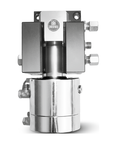
The press clamping force measuring system includes a wired or wireless display unit, measuring cable (if wired), and a force-sensing clamping head, inverted and customized to the press clamping mechanism specifications.

Force data from a wireless sensor can be actively uploaded to a PC or tablet, and would be compatible with ForceCheck sensor reading software that converts the data to automatically graph a force-time relationship and export to a spreadsheet (Excel/CSV) format. Advantages to this include the ability to track and predict press clamping issues before they occur and prevent the risk of halting production unnecessarily.Press clamping gauge readings could indicate a potential failure to occur in the future if the force drops over a long period of time. A number of problems could cause this to happen not necessarily related to the clamping mechanisms. While following the troubleshooting instructions or checklist of a die press system setup, a red flag during regular preventive maintenance could indicate:
-
A leak, failure, or a reduction of pressure in the hydraulic system
-
Quick-die-change mechanisms may require lubrication, maintenance, or adjustment
-
A loss of mechanical or hydraulic pressure adjustment or offset
When a press clamping system leaves the quality threshold, or goes below a minimum-average clamping/pressing pressure, it is an indication of a possible future catastrophic failure with the entire pressing system.
In the case of regular PM, the cost of PM equipment itself is clearly less than the potentially high repair costs of downed machinery and a halted production line when problems can be detected and fixed early. The quality of the press force gauge PM equipment is also of concern – while some manufacturers might get away with having cheap and lower-end force checking equipment, it is still a risk. ForceCheck clamping gauges are designed to specification by engineers with vast experience with the clamping-mechanism being checked itself, rather than a hunk of metal that just measures a number on a dial gauge. Instead, ForceCheck sensors offer the correct force-measurement range and calibration needed for the die clamping mechanisms. ForceCheck clamp and pressure checking gauges are more of a necessity than an accessory for die press clamping inspectors and operators, since PM is most likely already a priority.
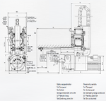
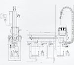
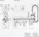
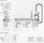
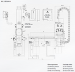
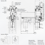
The press clamping head sensors are designed to be an inverted version of the clamping-mechanism it measures. There may be other requirements involved, such as a flange and/or locking mechanism to act like the clamp itself, as well as be durable enough to withstand and accurately measure the press clamping tension. Clamping head sensor designs are not limited to manufacturer and may be retrofitted to other specifications if needed.
For more information regarding this item (Quick Die Press Clamping Force Gauges) or other items, fill out the form below
or contact our office directly:
Telephone: 815-962-5600
Fax: 815-962-4600
Location: 304 North Main St, Suite 104, Rockford, IL 61101-1101 USA
Email: infο@ΤΑCRοckfοrd.cοm
Related
Automatic Electromechanical Bellcrank Lever Style Clamping Systems
Electromechanical clamp for die clamping on press slides. The clamp automatically travels between the parking position and the actual die, guided by the T-slot of the slide. The bell-crank lever covers a wider clamping range.
Automatic Electromechanical Drawbar Style Clamping Systems
The electro-mechanical self-locking drawbar style clamping system is designed for quick clamping dies of different widths with clamping slot on press slides. The clamping systems are controlled de-centrally and individually in each clamping system. Each local clamp control system communicates with the pressing machine control system. The clamping actuator automatically moves into the T-slot of the press slide between the parking position and the respective die. The electro-mechanical clamping system clamps the die and switches off automatically on reaching the clamping force.

Manual Hydro-mechanical Self-locking C-clamping Systems
The hydromechanical self-locking (hydrolock) C-clamping die clamping system is designed for clamping dies of various widths on press slides. The clamping actuator can be moved manually in the T-slot of the press slide between the parking position and the respective die. Hydraulic pressure is at a maximum 90 bar.
Automatic Hydraulic C-clamping Systems
The C-clamping hydraulic die clamping system is designed for clamping dies of various widths on press slides. The clamping actuator moves automatically in the T-slot of the press slide between the park position and the respective die. Hydraulic pressure is at a maximum 400 bar
Automatic Hydro-mechanical Self-locking C-clamping Systems
The C-clamping hydromechanical self-locking (hydrolock) die clamping system is designed for clamping dies of various widths on press slides. The clamping actuator moves automatically in the T-slot of the press slide between the parking position and the respective die. Clamping and unclamping are performed by a hydromechanical self-locking clamping gear. Hydraulic pressure is at a maximum of 90 bar.
Automatic Hydraulic Drawbar Style Clamping Systems
The hydraulic die clamping system with drawbar style clamping is designed for clamping dies of different widths on press slides. The clamping actuator moves automatically into the T-slot of the press slide between the parking position and the respective die. The clamping element can clamp different clamping rim heights due to the long clamping stroke of the double acting cylinder. Hydraulic pressure is at a maximum 400 bar.
Manual Hydro-mechanical Self-locking Drawbar Style Clamping Systems
The hydromechanical self-locking (hydrolock) drawbar style die clamping system is designed for clamping dies of various widths on press slides. The clamping actuator can be moved manually in the T-slot of the press slide between the parking position and the respective die. Hydraulic pressure is at a maximum 90 bar.
Manual Hydraulic C-clamping Systems
The hydraulic C-clamp die clamping systems are designed for clamping tools and dies of different widths on press slides. The C-clamp is equipped with a non-return valve. The die clamps can be manually moved in the T-slot of the press slide between the parking position and the respective tool. Hydraulic pressure is at a maximum 400 bar.
Automatic Hydro-mechanical Self-locking Drawbar Style Clamping Systems
The drawbar style hydromechanical (hydrolock) self-locking die clamping system is designed for clamping dies of various widths on press slides. The clamping actuator moves automatically in the T-slot of the press slide between the parking position and the respective die. Clamping and unclamping are performed by a hydromechanical self-locking clamping gear. Hydraulic pressure is at a maximum 90 bar.