410.310.132.000
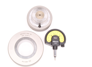
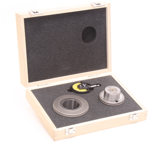
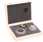
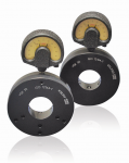
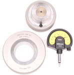
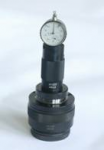
Dial Indicator Spindle Taper Gauges - HSK-A/C/E 32 + HSKB/D/F 40
For the periodic verification of the taper of HSK spindles per DIN 69063
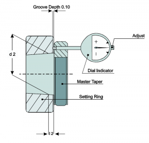
| HSK | d2 | l 2 | Part Number | |||||
|---|---|---|---|---|---|---|---|---|
| HSK-A/C/E 32 + HSKB/D/F 40 | 24 | 3.2 | 410.310.132.000 | |||||
| HSK-A/C/E 40 + HSKB/D/F 50 | 30 | 4 | 410.310.140.000 | |||||
| HSK-A/C/E 50 + HSKB/D/F 63 | 38 | 5 | 410.310.150.000 | |||||
| HSK-A/C/E 63 + HSKB/D/F 80 | 48 | 6.3 | 410.310.163.000 | |||||
| HSK-A/C/E 80 + HSKB/D/F 100 | 60 | 8 | 410.310.180.000 | |||||
| HSK-A/C 100 + HSKB/D/F 125 | 75 | 10 | 410.310.190.000 | |||||
| HSK-A 125 | 95 | 12.5 | 410.310.192.000 | |||||
| HSK-A 160 | 120 | 16 | 410.310.196.000 |
For more information regarding this item (Dial Indicator Spindle Taper Gauges - HSK-A/C/E 32 + HSKB/D/F 40) or other items, fill out the form below
or contact our office directly:
Telephone: 815-962-5600
Fax: 815-962-4600
Location: 304 North Main St, Suite 104, Rockford, IL 61101-1101 USA
Email: infο@ΤΑCRοckfοrd.cοm
Related
HSK Dial Indicator Spindle Taper Gauge Manual
Instruction manual for the dial indicator spindle taper gauge (410.310)
Series 410 Dial Indicator Tool Taper Gauges
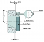
Both measuring gauges are set to zero with the calibrated taper plug gauge. When an HSK tool holder is inserted in the ring gauges, deviations in diameters d2 or d3 are shown on the indicator.
Dial Indicator Spindle Taper Gauges
To ensure sustained accuracy at HSK interfaces, we recommend comparison measuring of the geometry of HSK tool shanks and spindles at regular intervals. These checks should become more frequent with an increased change rate at the interface. Calibration on request.
Pneumatic Spindle Taper Gauges
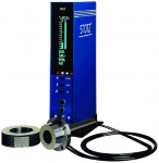
Non-contact measuring with nozzles results in high accuracy and consistency of measuring results. The measuring range can be increased with the built-in dial indicator. This enables the gauge to be used during pre-machining of the taper. Measuring set with case includes nozzle plug gauge with dial indicator and 2 setting rings.
Steep Taper Spindle Taper Dial Indicator Gauge
TAC Rockford's steep taper spindle gauge is designed to verify and measure correct location of the spindle gauge line.
The gauge comes as a complete set with carrying case, dial indicator, and master taper for setting the dial indicator
HSK Tool Holder Taper 30 Degree Clamping Angle Gauges
Using the calibrated master, the distance of the 30 degree clamping slope relative to l 2 is preset using the dial indicator holder. The tool taper to be measured is placed in the centering piece, allowing the variation of the taper to be measured.
Tool Holder Drive Key Tool Taper Gauges
Available for HSK 32, 40, 50, 63, 80, 100, 125, 160
Drive Key Spindle Gauges
When inserted in the spindle, the "go" gauge should be in contact with the plane face. The "no go" gauge should not contact the face. Two measuring gauges in storage case: "go" and "no go" plug gauges.
Centro Setup Indicator
With the CENTRO, bores and shafts can be easily and precisely centered. The CENTRO is clamped into a tool holder and inserted into the spindle of the milling machine. The machine spindle is then positioned near the bore or shaft that is to be measured, and rotates at low speed.
Spindle Runout Test Arbor Instructions
One of the leading causes of tool breakage, part finish issues, tolerance control, and machine registration issues is excessive spindle runout.

