570.120
Centro Setup Indicator
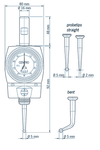
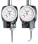
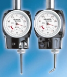
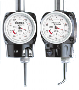
With the CENTRO, bores and shafts can be easily and precisely centered. The CENTRO is clamped into a tool holder and inserted into the spindle of the milling machine. The machine spindle is then positioned near the bore or shaft that is to be measured, and rotates at low speed.
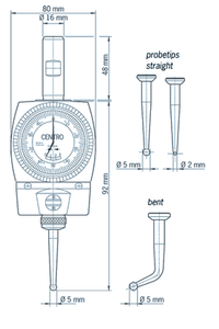
| Item | Probe Ø | Shaft Ø | Accuracy | Max. Rotation | Part Number | |||
|---|---|---|---|---|---|---|---|---|
| Centro Centering Indicator w/ Straight Probe Tip | 5 mm | 16 mm | .003 mm | 150 rpm | 80.300.00 | |||
| - | 16 mm | .003 mm | 150 rpm | 80.300.00.FHN | ||||
| Centro Straight Probe Tip with Ball | 5 mm | - | .003 mm | 150 rpm | 80.301.00 | |||
| Centro Bent Probe Tip with Ball | 5 mm | - | .003 mm | 150 rpm | 80.302.00 | |||
| Centro Straight Probe Tip with Ball | 2 mm | - | .003 mm | 150 rpm | 80.303.00 |
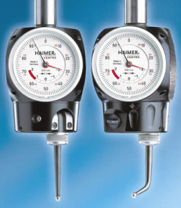
CENTRO provides quick and precise location of the centers of bores and shafts.With the CENTRO, bores and shafts can be easily and precisely centered. The CENTRO is clamped into a tool holder and inserted into the spindle of the milling machine. The machine spindle is then positioned near the bore or shaft that is to be measured, and rotates at low speed. The probe tip of the CENTRO then slides along the inside or outside surface of the diameter. Initially, the probe tip will be deflected and the amount of deflection is registered on the large dial. The stationary dial face does not turn with the spindle and therefore can always be seen by the operator. The position of the spindle must be corrected until the hands of the dial indicator stop moving. The spindle axis is now perfectly aligned with the diameter center.
The perpendicularity of a surface to the spindle may be inspected or adjusted in the same way. Concentricity errors of the spindle may be controlled or adjusted as well. Tramming of lathe turrets is also possible with the CENTRO. Shafts and bores can be measured with the same CENTRO, with a simple switch of a button, adjusting the direction of tension. Concentricity errors of the spindle or the clamping are compensated without the need of adjustment. The large easy to read dial face makes quick and accurate readings possible. The probe tips are interchangeable. There are several different probe tips to chose from for multiple applications.
For more information regarding this item (Centro Setup Indicator) or other items, fill out the form below
or contact our office directly:
Telephone: 815-962-5600
Fax: 815-962-4600
Location: 304 North Main St, Suite 104, Rockford, IL 61101-1101 USA
Email: infο@ΤΑCRοckfοrd.cοm
Related
3D New Generation Setup Indicator
The 3D-Sensor NG is a further development of our worldwide accepted and proven Universal 3D-Sensor. Its distinguishing features are improved mechanics and a new and compact design.
3D Digital Setup Indicator
The digital display has large numbers that measure in increments of 0,001mm. It can be easily read from a long distance (i.e. when mounted on a large machining center). The digital display is splash-proof and dust-proof and can be stored in the tool magazine of the machine.
Zero Master Digital Setup Indicator
The dial gauge indicates the distance between spindle axis and workpiece edge. As soon as the gauge shows zero, the spindle axis is exactly on the workpiece edge on the first attempt. This eliminates calculating or problems with positive or negative signs.
Zero Master Analog Setup Indicator
The Zero Master is the smallest 3D-Sensor worldwide. Usage, function and accuracy are equal to the Universal 3D-Sensor. The size of the Zero Master is adapted to small machines. The clamping shank has a diameter of 10 mm. Thus it can be also used on machines with ISO 30 or with small HSK spindles. The housing is shortened and does not protrude far out of the spindle so that even big work pieces can be measured. The Zero Master can be read with a small analog dial gauge.
HSK Dial Indicator Spindle Taper Gauge Manual
Instruction manual for the dial indicator spindle taper gauge (410.310)
Tool Holder Taper Complete Measuring Units
Calibrated with a gauge master, the taper gauge checks large taper diameter, small taper diameter, straightness of the taper, relationship of the flange to the taper, and taper length.
3D Universal Setup Indicator
Short and long probes are available. The sensor probes may be changed without any tool. No re-calibration of the unit is needed during a sensor probe change over. Simply bring the needle to Zero, and that is your edge with any probe. The accuracy is such that you are able to inspect your parts right on the machine.
Steep Taper Spindle Taper Dial Indicator Gauge
TAC Rockford's steep taper spindle gauge is designed to verify and measure correct location of the spindle gauge line.
Not included are an indicator and taper sleeve master.
The gauge can be used with any dial indicator with an 8mm stem. Recommended available options:
Part Nr. 499.220.150
- 0.01mm Resolution
Part Nr. 499.220.151
- 0.001mm Resolution
Part Nr. 499.220.155
- 0.00005" Resolution
In addition, we strongly recommend a 430.110 series Taper Sleeve Gauge to zero the indicator.
Series 410 Dial Indicator Tool Taper Gauges
Both measuring gauges are set to zero with the calibrated taper plug gauge. When an HSK tool holder is inserted in the ring gauges, deviations in diameters d2 or d3 are shown on the indicator.

