
240.322
Application: Hydrostatic Linear Motor Guide
")
Linear motors are used on high-speed machine tools with high acceleration and slide speeds. For slides with linear motors, HYPROSTATIK has developed hydrostatic guideways that have no wear, excellent damping characteristics, high stiffness and much lower friction when compared with ball or roller rails.
![]() PDF Data Sheet: Application: Hydrostatic Linear Motor Guide (240.322)
PDF Data Sheet: Application: Hydrostatic Linear Motor Guide (240.322)
New hydrostatic guideway for linear motorsLinear motors are used on high-speed machine tools with high acceleration and slide speeds. For slides with linear motors, HYPROSTATIK has developed hydrostatic guideways that have no wear, excellent damping characteristics, high stiffness and much lower friction when compared with ball or roller rails.
The secondary part of a synchronous linear motor is the permanent magnet field, which results in enormous attraction forces. The high attraction forces, combined with high acceleration and speed, mean conventional ball- or roller guideways are not always a design option. High speed, high acceleration and oscillation movements lead to increased wear of the balls or rollers, sealing lips and backlash. Dirt or chips which get past the sealing lips are coined in the rail surface. The permanent existing attraction force of 26000 N to 30000 N at a drive force of 10000 N places an additional load on the guide system and leads to short life in ball- or roller systems. The wear results in reduced stiffness in the guideway and, in extreme cases, to clearance, poor guide quality, and inaccurate positioning.
HYPROSTATIK has developed a hydrostatic guideway designed for the support of linear motors. The guideway does not wear, has excellent damping characteristics, is dynamically stiff, and has much lower friction when compared with ball or roller rails.
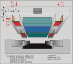
FunctionOn hydrostatic guideways, the hydrostatic pockets perform the load carrying instead of balls or rollers. Before starting, the slide rests on the guideways (red – see schematic). When the machine is turned on, the hydraulic pump supplies filtered oil to the PM-flow controller (pink), which then distributes it to the pockets (yellow). The pressure in the vertical pockets increases until the load of the slide weight and the magnetic force is equalized. The slide is then suspended about 0.001 inch from the guideway. The oil exits the pocket through this clearance and flows back to the hydraulic tank. A continuous supply of oil keeps the pressure in the pocket constant. When the pocket is additionally loaded by machining, acceleration, or weight forces, the PM-flow controller increases the pocket pressure and flow to keep the gap virtually constant. In an optimized design, the hydrostatic guideway is not influenced by hydrodynamic effects and viscosity changes, so the high stiffness and load capacity is basically independent of the speed of the slide and the temperature of the oil.
Wear FeaturesIn a working hydrostatic guideway, the slide is always suspended on the oil pad of the hydrostatic pockets, independent of speed, load and temperature. This means that the guide surfaces are never in contact while in use and wear is not possible. Machine features such as stiffness, load capacity, guide precision, positioning precision, and damping remain constant over years of operation.
DesignThe hydrostatic guideway for linear motors shown in the graphic has no retainers. The attraction force of the linear motor magnet replaces the prestress of the retainers used on standard guideways. This open guideway can also be used at an angle or vertically if the tilt- or lifting forces allow this, and the guideway is not lifted. If lifting forces are high, the guideway can be designed with additional hydrostatic pads.
Some linear motor designs use two linear motors in opposite directions so the magnetic forces cancel each other out. Disadvantages of this design are a very tall slide design, and stress from bending forces on the guideway or slide. Additionally, there are added costs for the second linear motor. With a hydrostatic system, the design height of the guideway and the linear motor between the slide plate and the guide plate is small – only about 2 inches.
The load capacity of hydrostatic pockets can be modified by changing the pocket size and the pump pressure. The stiffness of the pocket depends on the load and the flow control. Depending on magnetic force and slide weight, the stiffness of a hydrostatic pocket at the edge of the slide is between 600 lbs/0.0001 inch and 6000 lbs/0.0001 inch (»1000 N/micro-m and 10000 N/micro-m).
Friction and PositioningThe friction of hydrostatic guideways is proportional to the speed. At low speeds, friction is almost non existent. A light tap with a finger can move a 200kg slide.
The reverse-direction play and friction increase found with ball and roller guideways does not exist on hydrostatic guideways. The friction force of hydrostatic guideways can be tailored to nearly any requirement by changing the pad surface area, oil viscosity and gap size. Using a PM-flow controller from HYPROSTATIK, the friction is almost independent of the load, especially at low speeds – 100 to 1000 times lower than on ball guideways. The precision of positioning, the smallest movement and the slowest movement of the hydrostatic supported slide are only limited by the linear motor's resolution and the CNC control.
DampingThe hydrostatic pocket design can be optimized by working with HYPROSTATIK. A correct design allows excellent absorption of the excitation frequency, which is especially beneficial in machine tools. Chattering from standing waves is suppressed, the cutting power is increased, the tool life is prolonged, and workpiece finish is improved when compared to ball or roller guideways.
Production CostsThe hydrostatic pockets (yellow/red) are machined into the slide at nominal additional cost. No additional space for the roller pad and rail is necessary. The surface around the pockets in the slide (red) and the mating areas are the functional surface of the guideway. These surfaces are responsible for the guideway precision and can be produced by precision milling, grinding or forming. The function of the hydrostatic system is independent of the material and the surface hardness of the guideway. The choice of the surface and the material depends only on the required material stiffness, emergency features, and stability during transport.
Assembly and TestingOn ball guideways, deformation by improper mounting of roller pads or railways can lead to premature wear and malfunction. By measuring the pocket pressure during the stroke, proper assembly and function of the hydrostatic guideway can be monitored easily and inexpensively. With a pressure sensor connected to the CNC controller, it is possible to measure and monitor static and dynamic forces caused by weight, acceleration or machining during production.
Only filter and oil changes are needed to maintain the hydrostatic system. Dirt on the guideway is pushed away by the pocket or washed away by the constant oil fl ow. With a proper design, hydrostatic guideways have no problems if chips or coolant should enter the protective covers. For special applications, hydrostatic guideways without covers can be designed, where a seal around the pocket prevents mixing and entering of coolant.
Example: CNC LatheAt the exhibition IMTS '98 in Chicago, Hardinge Inc. Elmira, New York introduced their Concept 2000 machine with a hydrostatic cross slide and linear motor drive. The maximum speed demonstrated was 3000 inch/min (76 m/min) with an acceleration of 3 g (30 m/s²). Vertical stiffness at the edge of the table is over 2000 N/micro-m. Required oil volume of the hydrostatic guide is only about 0.5 l/min at 32 bar. Hardinge reports a precision of one axis 1 micro-inch (0.025 micro-m) and contour precision 2 micro-inch (0.05 micro-m). This results in an axis acceleration increase of up to 15 times, and up to 3 times faster cycle times.
Example: CNC GrinderIngersoll-Naxos in Langen in Germany makes grinders for cam- and crank shaft grinding with a hydrostatic supported cross slide with a V-flat design. Both axes are driven by linear motors. The precision and damping characteristics of the hydrostatic system produce excellent grinding results.
Example: Ultra-Precision Milling MachineKugler in Salem Germany successfully uses hydrostatic guideways with linear motors in their 3 to 5 axis Micro-Machining center for ultra-precision
For more information regarding this item (Application: Hydrostatic Linear Motor Guide) or other items, fill out the form below
or contact our office directly:
Telephone: 815-962-5600
Fax: 815-962-4600
Location: 304 North Main St, Suite 104, Rockford, IL 61101-1101 USA
Email: infο@ΤΑCRοckfοrd.cοm
Related
Hydrostatic Linear Motor Guide
The PM Flow Controller makes it possible for machine builders to easily integrate custom hydrostatic systems into both new and existing machines.
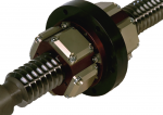
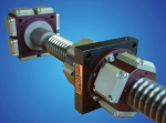
Hydrostatic Leadscrews
- Speed comparable to a linear motor - Very low friction when machining, virtually frictionless during positioning - Steps in the 0.1 micron range are possible - No backlash when reversing direction
CBN Hydrostatic Grinding Spindle Systems
This is an example of a hydrostatic spindle designed for high speed grinding with CBN grinding wheels. The small bearing diameter in combination with high surface speed allows the use of CBN wheels even for undercuts in a camshaft application.

Application: Hydrostatic Rotary Tables
The world's largest gear and profile grinding machines use hydrostatic bearings.

Hydrostatic Application Worksheet
Download the PDF data sheet for the Hydrostatic Application Worksheet
Comparison: Hydrostatic Leadscrews, Linear Motors, and Ballscrews
Design limitations and problems in ballscrew applications lead to the development of linear motors and to wear-free hydrostatic leadscrews. In this article we introduce the hydrostatic leadscrew system from HYPROSTATIK Schönfeld GmbH and compare its technical features with linear motor drives and ballscrews.
Hydrostatic Lathe Spindles
- Very low friction will heat the spindle only slightly. Nearly all motor power gets to the workpiece. Heat that is generated is moved immediately out of the spindle area with the oil and cooled in the chiller. - No vibration from roller bearings for extremely smooth operation. - Excellent damping of vibration during grinding process, resulting in superior surface finish and workpiece accuracy. In addition, grinding wheels will stay sharp longer.

Hydrostatic Center Bearings
- Only one radial bearing - Moment and axial forces are carried by an axial bearing - Integrated clamping piston and rotating oil union for a hydraulic collet. The clamping piston is driven with hydrostatic oil and released with springs. - Extremely minimal friction (results in minimal warming during continuous operation, and more of the motor drive force applied to the workpiece).

Hydrostatic Grinding Spindles with Integral Motors
- Very low friction will heat the spindle only slightly. Nearly all motor power gets to the workpiece. - Heat that is generated is moved immediately out of the spindle area with the oil and cooled in the chiller. - No vibration from roller bearings for extremely smooth operation. - Excellent damping of vibration during grinding process, resulting in superior surface finish and workpiece accuracy. In addition, grinding wheels will stay sharp longer.