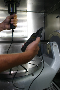
Why Check Drawbar Force?

Improve tool life and part finish
Correct tool holding force ensures that the spindle-tool holder interface is as rigid as possible.
A rigid interface will improve tool life by reducing chatter and excess wear, and in turn improve
workpiece finish.
Protect your spindles and ensure machining accuracy
Insufficient tool holding force can quickly wear or damage the critical spindle taper resulting in loss
of machine accuracy and an expensive repair bill.
For the HSK taper, wear and damage on the spindle taper are even more detrimental. The HSK taper relies
on an interference fit between the spindle and tool holder tapers, meaning drawbar force must be sufficient
for the tool holder to properly seat. Because the HSK interface seats both on the tool holder taper and flange,
dimensional tolerances are extremely tight. For HSK forms E and F, correct clamping force is crucial because
there are not drive keys or dogs to transmit torque–the system relies entirely on the power drawbar's
holding force.
Predict problems with the spindle's Belleville / disk spring stack
Machining centers with automatic tool clamping systems typically use Belleville/disk spring stack to
hold a tool in the spindle, with a hydraulic cylinder used to overcome the spring force to unclamp the tool.
High RPM is often an important design criterion for a spindle, meaning the use of small diameter bearings
makes sense from an engineering standpoint. Small bearings necessitate the use of small diameter springs to
fit into the spindle arbor. Small-diameter springs lead to highly stressed springs for tool clamping, and even
more so during tool unclamp.
A typical drawbar spring stack is designed to last approximately 1 million cycles. This may sound like a big
number, but tool changes add up quickly. An example: a process with 3 to 4 tool changes per minute (many do much
more), with 2,000 operating hours per year (one shift), means between 360,000 and 480,000 cycles are
made per year. In this scenario, the springs have reached the end of the design life cycle and should
be replaced after two years. We have found some processes that reach 1 million cycles after 6 months–with
the complaint that the "springs break all the time."
Springs will not break all at once. Initially only one spring might break without significant impact on tool
holding force. However, soon others will break since they have to do the work of the broken spring (or springs)
as well. The rest of the springs will be overloaded and break or take a permanent set.
This failure process can be detected with a clamping force measuring device and action be taken before the
clamping system fails completely.
Check for the role that friction plays in the clamping system and for proper lubrication
Some drawbar designs use a mechanical force intensification mechanism to increase tool holding force. When
force intensification is used, friction is a factor to be watched. It is difficult to quantify friction without
measurement. Machine builders typically provide a tool holding force specification for properly lubricated and
adjusted clamping system.
Most power drawbar systems with HSK tapers use force intensification in the gripper design. The mechanical
intensification of the force is typically between 3 and 9 times, making friction a major factor in the proper
operation of the system.
For systems with manual HSK grippers such as those supplied by Mapal and Guehring, periodic verification of
correct tool holding force is also of critical importance. Per manufacturer recommendation, tools should be
clamped using a torque wrench to ensure correct force. However, if the gripper is not properly lubricated,
tool holding force will be much lower at the specified torque.
Operator safety
Eventually, the tool holding system of a machine will fail catastrophically if left unchecked. There will
be lots of mysterious problems such as poor part finish and broken tools, and eventually leading to the tool
flying out of the spindle and damaging the workpiece, machine, or worse–injuring the operator.
Standards compliance
- The ISO and DIN HSK standards have recommended minimum clamping forces. The ForceCheck gauge can verify that these are met.
- The "CAT" steep taper standard ASME B5.50 specifically recommends using a drawbar force gauge.
- ISO 9000 compliance requires that critical machine parameters be periodically checked.
HSK Taper
Measuring bars, complete sets, and base sets for all HSK type spindles. Contact us for other wireless and carrying case options.
Steep Taper (MAS 403 BT)
Measuring bars, complete sets, and base sets for Steep Taper (MAS 403-BT) JIS standard.
Steep Taper (SK-DIN)
Measuring bars, complete sets, and base sets for Steep Taper (SK) DIN standard. Metric or inch retention knob / pull-stud threading available on each measuring bar.
Steep Taper (CAT/ANSI)
Measuring bars, complete sets, and base sets for Steep Taper (SK) CAT-ANSI. Metric or inch retention knob / pull-stud threading available on each measuring bar.
Steep Taper (ISO)
Measuring bars, complete sets, and base units for measuring drawbar force on a Steep Taper (SK) ISO standard spindle.
PSK
Measuring bars, complete sets, and base units for measuring drawbar force on Coromant Capto spindles (Polygonal Shank Taper - PSK).
KM Taper
Measuring bars, complete sets, and base units for measuring drawbar force on a Kennametal KM spindle.
Contact us for more information
To make an inquiry, use this form and we will get back to you
as soon as we can. To send photos or more information, please
email us
with any attachments.
Telephone: 815-962-5600
Fax: 815-962-4600
Location: 304 North Main Street, Suite 104, Rockford, IL 61101 USA
Email: infο@ΤΑCRοckfοrd.cοm
